One of the things that I considered easy was working with IMU (Inertial Measurement Unit), but I have found a few challenges. IMU normally refers to an electronic device which has an accelerometer and gyroscope that measure the body-specific force, angular rate, and orientation. They are everywhere: from your watch, earplugs, mobile phone, or lawnmower.
These devices are great, but tons of different variables may affect their performance. I’ll break down the difference between accelerometers and gyroscopes, how they work, and how to get the best out of their measurements.
Types of accelerometer
Almost all accelerometers work by measuring the capacitance between fixed and movable electrodes to determine acceleration. It measures acceleration in gravity units (G), so 1G = 9.81 m/s². Since you’re only getting acceleration, you can measure 3 Degrees of Freedom (x, y, and z).
There are several types of accelerometer technologies:
- Capacitive: The most common in all devices/projects, they measure capacitance between fixed and movable electrodes to determine acceleration. They aren’t the most accurate, but the power efficiency, size, and cost are unbeatable.
- Piezoelectric: They generate an electrical charge in response to mechanical deformation caused by acceleration. It's more accurate than Capacitive and Piezoresistive accelerometers but consumes more energy, is a bit bigger than Capacitive, and is more expensive. Explanation link
- Piezoresistive: They utilize changes in resistance within a semiconductor material due to mechanical stress caused by acceleration. Same accuracy as Capacitive, but consumes more power and it's bigger than capacitive. Exlanation link
- Optical: They measure changes in light interference in response to acceleration. This is the most accurate technology, but size and cost are high. For example, this is the type of technology used in space rockets to measure high-altitude winds and make corrections when returning to Earth. Explanation link
How capacitive accelerometer works
The most used accelerometer measures acceleration by detecting changes in capacitance. Inside the device, there is a suspended proof mass (shown in orange), held in place by tiny springs (black). Surrounding the proof mass are fixed plates. When the accelerometer experiences movement, the proof mass shifts, causing the distance between the plates to change. This alters the capacitance, which can then be accurately measured (highlighted in the red boxes).
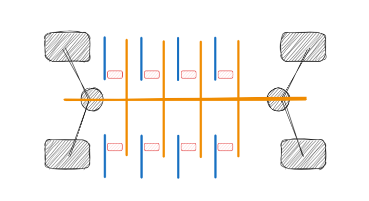
As the proof mass moves closer to or further from the fixed plates, the capacitance varies accordingly. This principle allows the accelerometer to sense acceleration. However, because capacitance is also sensitive to factors like temperature, accelerometer readings can be influenced by environmental changes as well. You can see how it works here
Gyroscope
Normally, accelerometers alone are not 100% reliable, and the plates can vibrate, so using sensor fusion algorithms, and measurements from other instruments, like Gyroscopes, helps to get more reliable measurements.
Similar technology to gyroscopes has been with us since Classical Greece. The main use cases were found in 1743, when John Serson used some kind of gyroscope for ships, to locate the horizon in foggy conditions. In the 20th century, during the world wars, gyroscope usage was fundamental for submarines and airplanes. I highly recommend understanding how Foucault's gyroscope works, and his demonstration of the rotation of the Earth.
A MEMS gyroscope consists of a suspended proof mass, a driving system to oscillate the proof mass with some springs. The Coriolis effect causes changes in the vibration pattern, and these changes are detected and measured to get the angular rotational rate and orientation. So gyroscopes add a way to measure rotation and twist.
How Gyroscope works
This is just a short summary, but if you have thirty minutes, I highly recommend this post. In a nutshell, the capacitive gyroscopes are measuring the capacitance from a free mass connected with springs. In the following diagram, you can see how the springs are moving, and how the capacitance is measured in different cases. The black box is a fixed mass, and green ones are the moving parts, at the end connected to the electrodes.
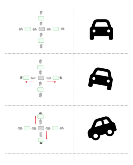
You can also see how the Coriolis force affects the mass in the same axis. Here is a nice example.
Euler angles and quaternions
Now that we understand how accelerometers and gyroscopes help us measure movement and rotation, the next step is to determine how to represent this data in 3D space. This is where concepts like Euler Angles and Quaternions are here to help us:
Euler Angles:
Euler angles describe orientation using three consecutive rotations around the X, Y, and Z axes. Usually, these are called roll (rotation around X), pitch (rotation around Y), and yaw (rotation around Z). It's easy to visualize and understand, but Euler angles have a critical problem: gimbal lock. Gimbal lock happens when two of the three rotation axes align, causing a loss of one degree of freedom — meaning you can't represent all possible orientations smoothly. Gimbal lock was a problem during the Apollo 13 mission.
Quaternions:
Quaternions are a more advanced way of representing rotations, using four numbers (x, y, z, w) instead of three angles. They are based on complex numbers and don't suffer from gimbal lock. Another big advantage is that interpolation between orientations (for example, in animations or smooth transitions) is much smoother and more stable with quaternions than with Euler angles. However, quaternions are harder to understand intuitively because they are more abstract. Regarding quaternions, I can only recommend reading this blog and watching these videos. Fun fact, quaternions were introduced in video games in the late 90s in Tomb Raider, to move the camera accordingly to Lara Croft.
Nowadays, almost all projects out there use quaterions under the hood, they are more reliable. For visualization Euler angles are preferred because are easier to read.
Quaterions on Rust
Once you have your orientation calculations in place using quaternions, the next challenge is to apply them practically. When using Rust, there are multiple math libraries. My favorite is Nalgebra. To get the quaternions, you can initialize them like this:
UnitQuaternion::from_scaled_axis(Vector3::new(x, y, z))
When you already have your quaternion, you can rotate like this:
let gravity_dir = Vector3::new(0.0, 0.0, 1.0);
let correction = UnitQuaternion::rotation_between(&gravity_dir, &accel_normalized)?
And you can display your Euler angles like this:
let euler = correction.euler_angles();
info!("roll='{:.2}' picth='{:.2}' yaw='{:.2}'", euler.0, euler.1, euler.2);
Sensor fusion
With all the information about accelerometers, gyroscopes, and quaternion math, we are still left with one major problem: how to combine the data. Accelerometers and gyroscopes alone are not perfect. Accelerometers have noise and can be affected by vibrations, and gyroscopes have integral drift over time. To fix this, we use sensor fusion.
Sensor fusion combines data from the accelerometer and gyroscope to get better measurements. The simplest method is the complementary filter, where you mix gyroscope measurements (fast changes) with accelerometer measurements (long-term stability). For more advanced systems, you should use a Kalman filter, or some special filters like Madgwick or Mahony filters, which are made specially for fusing IMU data (accelerometers + gyroscopes).
With sensor fusion, you can get stable and accurate roll, pitch, and yaw values over time, without big errors or noise.
What helped me achieve better results
With all these tools and techniques in mind, I learned a lot by trial and error in my IMU projects. Here are some tips that helped me get better results:
- Sampling rate: Make sure you are reading the sensor fast enough, normally at least 50Hz or more, depending on your application and battery.
- Calibration: Sensors have small errors from the factory. You need to calibrate them to remove offsets, scale errors, and bad alignment. Almost all of them can be set using special registers inside the I2C. Nice example here
- Temperature: Temperature can change the behavior of the sensor, so calibration matters a lot.
- Filtering: Use simple low-pass or high-pass filters to remove noise and focus on the real signal you want.
For non-hardware developer like me, working with IMUs can seem easy at first, but the devil is always in the details! I learned all the details the hard way, but I hope this post gives you a reference guide in case you want to work with IMUs in the future.
PS: I’m using IMUs to track movement in my rehabilitation, trying to get as precise as possible to improve my recovery.